Touch Stack Options for a 0.39-Inch 1080p Micro OLED Module in AR Glasses
Touch on a 0.39-inch 1080p Micro OLED for AR glasses is a stack decision, not a display decision. The panel already fits 1920x1080 pixels and a stated 5644 PPI into a package small enough to sit inside the temple of a pair of glasses, which leaves almost no bezel and no depth for a conventional sensor layer. Resistive, discrete capacitive and on-cell routes all work in principle, but they differ in where the sensing electrodes sit, whether the wearer has to deflect anything, and how much of the emitter's light survives the extra interfaces. Fix the sensing principle first, then the mechanics and the bus, and the rest of the design follows from those two choices.
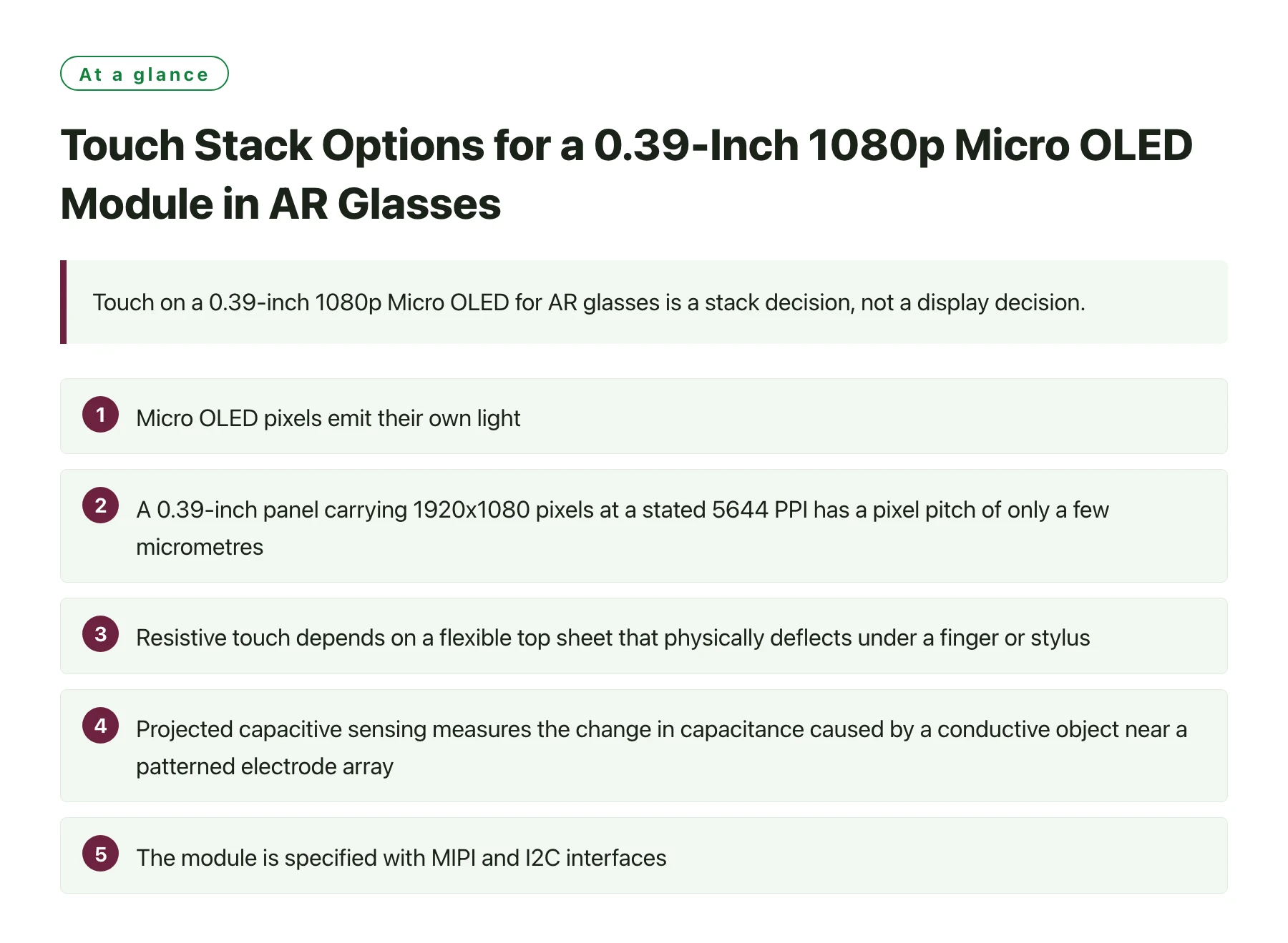
Key takeawaysMicro OLED pixels emit their own light, so there is no backlight cavity to hide a sensor stack in and anything placed in front of the panel sits directly in the optical path. [1] · A 0.39-inch panel carrying 1920x1080 pixels at a stated 5644 PPI has a pixel pitch of only a few micrometres, so electrode patterns, routing and alignment tolerances all have to be reasoned about at roughly the same scale as the pixels. [2] · Resistive touch depends on a flexible top sheet that physically deflects under a finger or stylus, which is hard to reconcile with the thin, coated and sometimes curved cover glass used in eyewear. · Projected capacitive sensing measures the change in capacitance caused by a conductive object near a patterned electrode array, so it needs no pressure and can operate behind a thin dielectric cover. [3] · The module is specified with MIPI and I2C interfaces, and MIPI DSI is a high-speed serial display interface, so the touch controller normally belongs on I2C where its low-rate traffic cannot disturb the pixel stream. [4]
The part in question is a 0.39-inch active-matrix Micro OLED module: 1920x1080 full HD, a stated 5644 PPI, 16.7 million colours, MIPI and I2C interfaces, and a published operating range that starts at -40 °C. Those numbers describe a display built for near-eye use, where the eye sits centimetres from the emitter and every layer between the two is visible in a way it never is on a phone.
AR glasses make the touch problem awkward for a second reason: the wearer's hands are usually busy, and the front surface is not a plain glass slab. It is often shared with the combiner or waveguide that carries the virtual image, it may be curved, and it normally carries an anti-reflective coating chosen for see-through optics. A sensor layer added late in the programme can force that coating, and sometimes the front optic itself, to be redesigned.
This article compares the three realistic touch routes for this class of panel, works through the electrical budget when the display already owns a MIPI link, and lists the mechanical, thermal and tooling checks that catch a bad stack before anyone pays for a mask set. The emphasis throughout is on decisions an integrator can actually verify at the bench.
Why 5644 PPI changes what a sensor layer can be
The number that drives every downstream choice is not the 0.39-inch diagonal, it is the pixel density. Pixel density is normally quoted as pixels per inch measured along the diagonal [2], and at a stated 5644 PPI the pitch between neighbouring pixels falls to roughly 4.5 micrometres. A finger-sized electrode pattern with a pitch of a few millimetres is therefore three orders of magnitude coarser than the image it is layered over, and the two periodic structures share the same few square millimetres of glass.
That mismatch is manageable, but it has two consequences that show up in production rather than on paper. First, the sensor's transparent conductors and their routing compete for space with the display's own driver routing, so how much bezel remains around the active area effectively decides whether the touch layer is manufacturable at all. Second, superimposing a periodic electrode grid on a periodic pixel array can produce moire, and a near-eye image gives the user no way to move further away from it.
The panel is also emissive: an active-matrix OLED that produces 16.7 million colours and switches pixels fully off for black. [1] There is no bright backlight budget in which to bury a transmission loss, and the deep black level that makes the display look convincing is exactly the state most easily lifted by a stray reflection from an added surface.
Where the sensor can physically sit
Four placements are practical. A discrete overlay film is bonded in front of the panel and is electrically independent of it, so it can be sourced separately and changed without touching the display revision. A cover-glass sensor patterns the electrodes onto the front optic itself, saving one lamination and one air interface but forcing the electrode pattern and the anti-reflective coating to be co-designed. On-cell touch forms the electrodes as part of the display substrate, removing the extra film but moving the constraint to the panel maker's process. In-cell touch goes further and integrates the electrodes into the display's own cell structure, which couples the sensor design tightly to the panel and its driver IC.
For a 0.39-inch part, the choice is usually made by z-height and by who owns the risk. As long as the sensor is a separate film, the integrator can iterate. As soon as it moves on-cell or in-cell, the schedule belongs to the panel supplier and the module becomes the gate on every mechanical revision.
What the eye notices that a bench photo does not
Transmission loss is the easy effect to measure and the least damaging. The effects that generate support tickets are faint sparkle where the electrode grid beats against the pixel structure, a slight haze across the whole image, and ghost reflections from the newly added surfaces. Near-eye optics are often paired with an anti-reflection or polarising layer to control ambient light, and inserting a sensor film changes where that layer can sit and how well it works.
The practical test is not a photograph through the stack but a worn prototype viewed against a bright background, because ambient light entering the optical path is what makes added interfaces visible. If the sensor pattern is detectable in that condition, no amount of controller tuning will hide it.
Comparing touch routes for a 0.39-inch AR display module
| Route | Sensing principle | Stack and optical impact | Realistic fit in AR eyewear |
|---|---|---|---|
| Resistive film | Pressure brings two conductive sheets into contact | Needs a compliant top sheet that deflects, so it cannot be rigidly bonded to a thin cover glass | Gloved or stylus input, field-service viewers, cost-driven designs |
| Discrete capacitive overlay | A finger changes the capacitance of a patterned electrode array | Adds a bonded sensor film plus a dielectric cover, so two extra interfaces sit in front of the emitter | Touch-first eyewear where the sensor and the front optic can share one glass |
| On-cell capacitive | Sensor electrodes are formed on the display substrate | Removes the separate sensor lamination but moves bonding and cover-glass constraints to the panel supplier | Compact eyewear where z-height, part count and assembly yield dominate |
| In-cell capacitive | Electrodes are integrated inside the display cell structure | Reduces add-on layers but couples the sensor design to the panel and its driver IC | High-volume products able to co-develop the panel with the supplier |
| No touch layer | Input handled by temple buttons, a ring, voice or gaze | Nothing is added in front of the emitter, so optical performance is untouched | Viewers worn for long sessions where the wearer's hands are occupied |
Bus budget when the display already owns MIPI
The module is specified with MIPI and I2C, and that combination is convenient for a touch design. MIPI DSI is a high-speed serial display interface that carries the pixel stream as packets over differential lanes [4], with tight timing expectations that leave little slack for unrelated traffic. A touch controller, by contrast, reports a handful of coordinates at a modest rate. Keeping touch on I2C means no coordinate transaction can land in the middle of a frame, and the display lanes stay dedicated to pixels.
A module such as the 0.39" MIPI Micro OLED display module ships without any touch layer, so the sensing route stays a decision the integrator can revisit at the next mechanical revision instead of a property of the panel.
Two habits make the separation work in firmware. First, drive the touch controller from its interrupt pin rather than polling it at full rate, and configure it to report only on state change, which drops bus load to almost nothing when nobody is touching the glasses. Second, keep touch handling below the display pipeline in the host scheduler; a capacitive report that triggers a blocking read in the same context as the frame update is a common source of a periodic stutter that looks like a panel fault.
If the host genuinely has to multiplex one bus between the panel and a touch controller, define the arbitration rule before the schematic is frozen. The rule has to answer a specific question: what happens when a frame must start while a touch read is half finished? The only honest way to settle it is to measure the display's worst-case frame timing with touch active, then repeat with the sensor covered so the controller sees a continuous stream of events.
One worst-case latency measurement taken with touch active is worth more than any average frame time taken with touch idle.
A review sequence that catches touch problems before tooling
- Write the optical stack down as a list. Record every layer between the emitter and the eye with its thickness and material. If the touch layer is not on that list with a thickness, the optical design is not finished.
- Decide whether the cover glass is the touch surface. Sharing the front optic with the sensor saves a lamination and a reflection surface, but it forces the electrode pattern and the anti-reflective coating to be co-designed and co-tooled.
- Fix the interface and the interrupt strategy early. Put touch on I2C, dedicate a controller pin to its interrupt line, and write down what the host does when a touch report and a frame update arrive in the same scheduler tick.
- Build a mechanical coupon rather than a product. A sensor bonded to the real cover glass on a dummy mount is enough to measure transmission loss, moire and touch sensitivity at the actual dielectric thickness.
- Test the stack while it is worn. Eyewear is touched at an angle, in motion and sometimes with cold or damp fingers, so a bench test at normal incidence will overstate the sensitivity margin you really have.
Thermal, tooling and supply questions that surface late
The module's published operating range starts at -40 °C, and a touch layer added in front of it has to survive the same storage and use conditions as the panel. In eyewear the stack is also warmed from two directions: the wearer's face on one side and the compute module in the temple on the other. Capacitive baselines drift with temperature and with the dielectric in front of the sensor, so a design calibrated once on the bench will behave differently after an hour against a warm head. Either choose a controller that re-baselines itself or budget firmware time for periodic recalibration.
Tooling is where the routes diverge commercially. A cover-glass sensor needs its own patterning and a bonding step with a defined tolerance, while on-cell and in-cell move that work to the panel supplier at the cost of volume commitments and longer lead times. Ask for the touch active area and the display active area as separate drawings rather than a single outline; where the two fail to overlap, the user gets a dead edge that reads as a software bug, and the overlap tolerance relative to the remaining bezel is what determines assembly yield.
Finally, treat the touch choice as a qualifiable revision of the module. A discrete film can be replaced without requalifying the panel, whereas an on-cell change reopens the display qualification, the optical stack measurement and any coating work done for the front optic. Deciding which of those you can afford to repeat is often what settles the argument.
Budget the touch layer as an optical component, not as an accessory. Every extra interface in front of an emissive panel costs transmission and adds a reflection surface, and at 5644 PPI even a faint sensor pattern sits inside the image rather than in the margins. If the added stack costs more than a point or two of transmission, the panel's specified output no longer describes what reaches the eye, and the brightness target has to be renegotiated rather than assumed.
Sources
Frequently asked questions
Can on-cell touch be added to a 0.39-inch Micro OLED module that ships without it?
Usually not at the module level, because on-cell electrodes are formed as part of the display substrate process rather than laminated on afterwards. That makes on-cell a panel-level decision to raise with the supplier early, ideally before the panel revision is frozen. If the panel cannot be changed, a discrete capacitive film or a sensor patterned onto the cover glass are the practical alternatives.
Will a capacitive touch layer visibly degrade the image in AR glasses?
It can, because the sensor adds at least one transparent layer and one interface in front of the emitter. The symptoms are a small transmission loss, faint sparkle where the electrode grid beats against the pixel structure, and extra ghost reflections from the added surfaces. How much a wearer notices depends on the electrode pitch, the cover thickness and whether the anti-reflective coating was designed for the final stack.
Should the touch controller share the MIPI interface used by the display?
No. MIPI DSI is a packet-based high-speed display interface, and mixing coordinate traffic into it complicates both the host driver and the frame timing budget. Keep touch on I2C with an interrupt line and reserve the MIPI lanes for pixels. If you have no choice but to multiplex, prove the display's worst-case timing with the touch controller active.
Is resistive touch ever the right choice for a 0.39-inch Micro OLED module?
It is the right choice when input has to work through gloves or with a passive stylus, which still happens in industrial and field-service viewers. The cost is mechanical: the top sheet must be able to deflect, so it cannot be rigidly bonded to a thin cover glass, and that compliant layer sits directly in the near-eye optical path. For consumer AR glasses with bare-finger input, capacitive sensing is the better match.
What should I ask a supplier before tooling a touch cover for eyewear?
Ask for the touch active area and the display active area as separate drawings, the cover-glass thickness and material the sensor was tuned for, and whether the controller re-baselines itself as temperature changes. Ask also about bonding tolerance relative to the visible area, because that tolerance together with your remaining bezel decides whether the design can be assembled at volume.